MARENG 3
UNIT 3
Below you will find a list of the vocabulary that has to be researched for the test of Unit 3,followed by additional research material that should be used, all in preparation for your test of Unit 3.
3.1 Definition of Port
A port is a location on a coast or shore containing one or more harbors where ships can dock and transfer people or cargo to or from land. Port locations are selected to optimize access to land and navigable water, for commercial demand, and for shelter from wind and waves. Ports with deeper water are rarer, but can handle larger, more economical ships. Since ports throughout history handled every kind of traffic, support and storage facilities vary widely, may extend for miles, and dominate the local economy. Some orts have an important, perhaps exclusively military role.
Dock (maritime)
A dock
(from Dutch 'dok')
is a human-made structure or group of
structures involved in the handling of boats or ships, usually on or close to a
shore. However, the exact meaning varies
among different variants of the English language. "Dock" may also
refer to a dockyard (or shipyard) where the
loading, unloading, building, or repairing of ships
History
The
world's oldest known dock at Lothal (2400 BCE) was
located away from the main current to avoid deposition of silt.[1] Modern oceanographers have
observed that the Harappans must have possessed great knowledge relating to
tides in order to build such a dock on the ever-shifting course of the Sabarmati, as well as exemplary hydrography and maritime engineering.[1] This was the earliest known dock
found in the world, equipped to berth and service ships.[1] It is speculated that Lothal
engineers studied tidal movements, and their effects on brick-built structures,
since the walls are of kiln-burnt bricks.[2] This knowledge also enabled them
to select Lothal's location in the first place, as the Gulf of Khambhat has the highest tidal
amplitude and ships can be sluiced through flow tides in the river estuary.[2] The engineers built a trapezoidal
structure, with north-south arms of average 21.8 metres (71.5 ft),
and east-west arms of 37 metres (121 ft).[2]
In British English, a dock is an enclosed area of water used for loading, unloading, building or repairing ships. Such a dock may be created by building enclosing harbour walls into an existing natural water space, or by excavation within what would otherwise be dry land.
There are two specific elaborations of the dock:
In American English, a dock is technically synonymous with pier or wharf—any human-made structure in the water intended for people to be on. However, in modern use, pier is generally used to refer to structures originally intended for industrial use, such as seafood processing or shipping, and more recently for cruise ships, and dock is used for most everything else, often with a qualifier, such as ferry dock, swimming dock, ore dock and others. However, pier is also commonly used to refer to wooden or metal structures that extend into the ocean from beaches and are used, for the most part, to accommodate fishing in the ocean without using a boat.
In American English, the term for the water area between piers is "slip".
In the cottage country of Canada and the United States, a dock is a wooden platform built over water, with one end secured to the shore. The platform is used for the boarding and offloading of small boats.
Wharf
A wharf, or quay (pronounced "key"), is a structure on the shore of a harbour where ships may dock to load and unload cargo or passengers. Such a structure includes one or more berths (mooring locations), and may also include piers, warehouses, or other facilities necessary for handling the ships.
A wharf commonly comprises a fixed platform, often on pilings. Major commercial ports typically hold large warehousing facilities that serve as interim storage areas, since the typical objective is to unload and reload vessels as quickly as possible. Where capacity is sufficient a single wharf with a single berth constructed along the land adjacent to the water is normally used; where there is a need for more capacity multiple wharves, or perhaps a single large wharf with multiple berths, will instead be constructed, sometimes projecting into the water. A pier, raised over the water rather than within it, is commonly used for cases where the weight or volume of cargos will be low.
Smaller and more modern wharves are sometimes built on flotation devices (pontoons) to keep them at the same level to the ship even during changing tides.
In everyday parlance the term quay is common in the United Kingdom and many other Commonwealth countries, whereas the term wharf is more common in North America. In commercial/industrial usage wharf is typically avoided with quay being used to refer to the berthing areas, and port and terminal being used to refer to the overall structures and locations. Merriam-Webster's Dictionary of Synonyms quotes the New York Times as saying "a quay is a docking facility at which vessels lie parallel to the shoreline."[2] In some contexts wharf and quay may be used to mean pier, berth, or jetty, though these uses are not addressed here.[2]
Etymology
The word comes from the Old English hwearf, meaning "bank" or "shore", and its plural is either wharfs, or, especially in American English, wharves; collectively a group of these is referred to as a wharfing or wharfage. "Wharfage" also refers to a fee ports impose on ships against the amount of cargo handled there.
In the northeast and east ofEngland Thames river boats.
Another explanation may be that the word wharf comes, like a lot of naval terms, from the Dutch word "werf" which means 'yard', an outdoor place where work is done, like a shipyard or a lumberyard.
Pier
A pier
is a raised structure, including bridge and building
supports and walkways, over water, typically supported
by widely spread piles or pillars. The lighter
structure of a pier allows tides and currents to flow almost unhindered,
whereas the more solid foundations of a quay
or the closely-spaced piles of a wharf can act as a breakwater,
and are consequently more liable to silting. Piers can range in size and
complexity from a simple lightweight wooden structure to major structures
extended over a mile out to sea. In American English, pier may be synonymous
with dock.
Piers have been built for several different purposes, and because these different purposes have distinct regional variances, the term pier tends to have different nuances of meaning in different parts of the world. Thus in North America and Australia, where many ports were, until recently, built on the multiple pier model, the term tends to imply a current or former cargo-handling facility. In Europe however, where ports have tended to use basins and river-side quays rather than piers, the term is principally associated with the image of a Victorian cast iron pleasure pier. However, the earliest piers such as Ryde and Brighton Chain pre-date the Victorian age.
Types of pier
Although with considerable overlap, Piers can be categorized into different groupings according to the principal purpose. For example, pleasure piers often also allow for the docking of pleasure steamers and other similar craft, whilst working piers have often been converted to leisure use after being rendered obsolete by advanced developments in cargo-handling technology.
Working piers
Working
piers were built for the handling of passengers and cargo onto and off ships or
(as at Wigan Pier) canal boats. Working piers
themselves fall into two different groups. Longer individual piers are often
found at ports with large tidal ranges, with the
pier stretching far enough off shore to reach deep water at low tide. Such
piers provided an economical alternative to impounded
docks where cargo volumes were low, or where specialist bulk cargo
was handled, such as at coal piers. The
other form of working pier, often called the finger pier, was built at ports
with smaller tidal ranges. Here the principal advantage was to give a greater
available quay length for ships to berth against compared to a linear littoral
quayside, and such piers are usually much shorter. Typically each pier would
carry a single transit
shed the length of the pier, with ships berthing bow or stern in to
the shore. Some major ports consisted of large numbers of such piers lining the
foreshore, classic examples being the Hudson River frontage of New York, or the Embarcadero
in San Francisco.
The advent of container shipping, with its need for large container handling spaces adjacent to the shipping berths, has made working piers obsolete for the handling of general cargo, although some still survive for the handling of passenger ships or bulk cargos. Many working piers have been demolished, or remain derelict, but others have been recycled as pleasure piers. The best known example of this is Pier 39 inSan Francisco
At Southport and the Tweed River on the Gold Coast in Australia, there are piers that support equipment for a sand bypassing system that maintains the health of sandy beaches and navigation channels.
Pleasure piers were first built in England, during the 19th century. The earliest structures were those at Ryde, built 1813/4, Leith(Trinity Chain) 1821 andBrighton (Chain)
1823. Only the oldest of these piers still remains. At that time the
introduction of the railways for the first
time permitted mass tourism to dedicated seaside resorts. However, the large
tidal ranges at many such resorts meant that for much of the day, the sea was
not visible from dry land. The pleasure pier was the resorts' answer,
permitting holiday makers to promenade over and alongside the sea at all times.
The longest Pleasure pier in the world is
at Southend-on-sea,
Essex, and extends 2,158 metres
(1.34 mi) into the Thames estuary.
The longest pier on the West Coast of the United States
Pleasure piers often include other amusements and theatres as part of the attraction. Such a pier may be open air, closed, or partly open, partly closed. Sometimes a pier has two decks.
Early pleasure piers were of wooden construction, with iron structures being introduced with the construction in 1855 of Margate Jetty, in Margate,England .
Margate England , and dates from 1860 - however the
worlds oldest iron pier[1]
dates from 1834 and is in Gravesend, Kent.
Gravesham council have recently purchased and refurbished this passenger pier.
Fishing piers
Many
piers are built for the purpose of providing land locked anglers access to
fishing grounds that are otherwise inaccessible.
The first recorded pier in England was Ryde Pier, opened in 1814 on the Isle of Wight, as a landing stage to allow ferries to and from the mainland to berth. It is still used for this purpose today. However it has had a leisure function in the past, with the pier head once containing a pavilion. There are still refreshment facilities today. The oldest cast iron pier in the world is Gravesend Town Pier, in Kent, which opened in 1834. However, it is not recognised by the National Piers Society as being a seaside pier.[2]
In their heyday, there were many pleasure piers acrossEngland
and Wales. These were found in most fashionable
seaside resorts during the Victorian era. There are still a
significant number of piers of architectural merit still standing, although
some have been lost. The most well known piers are perhaps the two at Brighton in East Sussex and the three at Blackpool in Lancashire. Two piers, Brighton 's
now derelict West Pier
and Clevedon Pier, were Grade 1 listed:Brighton
West lost its status after a series of fires and storms. The Birnbeck Pier in Weston-super-Mare is the only pier in the
world that is linked to an island. The National Piers
Society gives a figure of 55 surviving seaside piers in England and Wales
Scheveningen, the coastal resort town of The Hague, boasts the largest pier in the Netherlands, it was completed in 1961. A crane, built on top of the pier's panorama tower, provides the opportunity to make a 60 metres (200 ft). high bungee jump over theNorth Sea waves. The present pier is a successor of an
earlier pier, which was completed in 1901 but in 1943 destroyed by the German
occupation forces.
In Blankenberge a first pleasure pier was built in 1894. After its destruction in the World War I, a new pier was built in 1933. It remained till the present day, but was partially transformed and modernized in 1999-2004
Jetty
A jetty
is any of a variety of structures used in river,
dock, and maritime
works which are generally carried out in pairs from river banks, or in
continuation of river channels at their outlets into deep water; or out into
docks, and outside their entrances; or for forming basins along the sea-coast for ports
in tideless seas. The forms and construction
of these jetties are as varied as their uses; for though they invariably extend
out into water, and serve either for directing a current or for accommodating vessels, they
are sometimes formed of high open timber-work, sometimes of low solid
projections, and occasionally only differ from breakwaters
in their object. The term derived from the French word jetée,
"thrown", and signifies something thrown out. Jetties at the coast
that have been raised and extended, help prevent long shore drift, so therefore
slowing down beach erosion.
For regulating rivers
Another
form of jetties, wing dams are
extended out, opposite one another, from each bank of a river, at intervals, to
contract a wide channel,
and by concentration of the current to produce a deepening.
For berthing at docks
Where
docks are given sloping sides, openwork
timber jetties are generally carried across the slope, at the ends of which
vessels can lie in deep water or more solid structures are erected over the slope
for supporting coal-tips. Pilework jetties are also constructed in the water
outside the entrances to docks on each side, so as to form an enlarging
trumpet-shaped channel between the entrance, lock
or tidal basin and the approach channel, in order to guide vessels in entering
or leaving the docks. Solid jetties, moreover, lined with quay walls, are
sometimes carried out into a wide dock, at right angles to the line of quays at
the side, to enlarge the accommodation; and they also serve, when extended on a
large scale from the coast of a tideless sea under shelter of an outlying
breakwater, to form the basins in which vessels lie when discharging and taking
in cargoes in such a port as Marseille.
Dunkirk
At lagoon outlets
A
small tidal rise spreading tidal water over a large expanse of lagoon or inland
back-water causes the influx and efflux of the tide to maintain a deep channel
through a narrows no longer confined by a bank on each side, becomes dispersed,
and owing to the reduction of its scouring force, is no longer able at a
moderate distance from the shore effectually to resist the action of tending to
form a continuous beach in front of the outlet. Hence a bar
is produced which diminishes the available depth in the approach channel. By
carrying out a solid jetty over the bar, however on each side of the outlet,
the tidal currents are concentrated in the channel across the bar, and lower it
by scour. Thus the available depth of the approach channels to Venice through the Malaniocco and Lido
outlets from the Venetian lagoon have been deepened several feet over their
bars by jetties of rubble, carried out across the foreshore into deep water on
both sides of the channel. Other examples are provided by the long jetties
extended into the sea in front of the entrance to Charleston
harbour, formerly constructed of fascines, weighted with stone and logs, but
subsequently of rubble stone, and by the two converging rubble jetties carried
out from each shore of Dublin bay for deepening the approach to Dublin harbour.
Rivers
At the outlet of tideless rivers
Jetties
have been constructed on each side of the outlet river
of some of the rivers flowing into the Baltic, with the objects of prolonging the
scour of the river and protecting the channel from being shoaled by the littoral drift along the shore. The most
interesting application of parallel jetties is in lowering the bar in front of
one of the mouths of a deltaic river flowing into a tide — a virtual
prolongation of its less sea, by extending the scour of the river out to the
bar by banks. Jetties prolonging the Sulina branch of the Danube into the Black Sea, and the south pass of the Mississippi River into the Gulf of Mexico, formed of rubble stone and
concrete blocks, and respectively, have enabled the discharge of these rivers
to scour away the bars obstructing the access to them; and they have also
carried the sediment-bearing waters sufficiently far out to come under the
influence of littoral currents, which, by conveying away
some of the sediment, postpone the eventual formation of a fresh bar farther
out (see river engineering).
At the mouth of tidal rivers
Where
a river is narrow near its mouth, and its discharge is generally feeble, the
sea is liable on an exposed coast, when the tidal range is small, to block up
its outlet during severe storms. The river is thus forced to seek another exit
at a weak spot of the beach, which along a low coast may be at some distance
off; and this new outlet in its turn may be blocked up, so that the river from
time to time shifts the position of its mouth. This inconvenient cycle of
changes may be stopped by fixing the outlet of the river at a suitable site, by
carrying a jetty on each side of this outlet across the beach, thereby
concentrating its discharge in a definite channel and protecting the mouth from
being blocked up by littoral drift. This system was long ago applied to the
shifting outlet of the river Yare to the
south of Yarmouth, and
has also been successfully employed for fixing the wandering mouth of the Adur
near Shoreham, and
of the Adour flowing into the Bay of Biscay below Bayonne. When a new
channel was cut across the Hoek van Holland to provide a straighter
and deeper outlet channel for the river Maas, forming the approach channel to Rotterdam, low, broad, parallel jetties,
composed of fascine mattresses weighted with stone, were carried across the
foreshore into the sea on either side of the new mouth of the river, to protect
the jetty channel from littoral drift, and cause the discharge of the river to
maintain it out to deep water. The channel, also, beyond the outlet of the
river Nervion into the Bay of Biscay
has been regulated by jetties; and by extending the south-west jetty out for
nearly half a mile with a curve concave towards the channel the outlet has not
only been protected to some extent from the easterly drift, but the bar in
front has been lowered by the scour produced by the discharge of the river
following the concave bend of the south-west jetty. As the outer portion of
this jetty was exposed to westerly storms from the Bay of
Biscay before the outer harbour was constructed, it has been given
the form and strength of a breakwater situated in shallow water.
Berth (moorings)
A berth
is a location in a port or harbour used specifically for mooring
vessels while not at sea.
Locations in a Port
Berth
is the term used in ports and harbors to define a specific location where a vessel may
be berthed, usually for the purposes of loading and unloading.
Most berths will be alongside a quay or a jetty (large ports) or pontoons (small harbours and marinas). Berths are either general or specific to the types of vessel that use them in the process. The size of the berths varies from 5-10m for a small boat in a marina to over 400m for the largest tankers.
The following is a list of berth types that can be found in a large port.
Bulk Berth - used to handle bulk cargo. Vessels are loaded using either excavators and conveyor belts or pipelines. Storage facilities for the bulk cargo are often alongside the berth - e.g. silos or stockpiles.
Container Berth - used to handle 20' and 40' standard intermodal containers. Vessels are loaded and unloaded by container cranes, designed specifically for the task. Alongside the quay there is often a large flat area used to store both the imported and exported containers.
General Berth - used to handle smaller shipments of general cargo. Vessels using these would usually have their own lifting gear, but some ports will provide mobile cranes to do this.
Marina Berth - used to allow the owners of leisure craft on and off their boats. Generally alongside pontoons and accessed by hinged bridges (in tidal locations) to the shore.
Product Berth - used to handle oil and gas related products, usually in liquid form. Vessels are loaded via loading arms containing the pipe lines. Storage facilities for the products are usually some distance away from the berth and connected by several pipes to ensure fast loading.
X Berth - suitable for nuclear powered warships, and part of an operational Naval base or a building and refitting yard
Z Berth - suitable for nuclear powered warships, as a location for operational visits or stand offs
3.3 Port Facilities
International Ship and Port Facility Security Code
The International
Ship and Port Facility Security (ISPS) Code is an amendment
to the Safety of Life at Sea (SOLAS) Convention
(1974/1988) on minimum security arrangements for ships,
ports
and government agencies. Having come into force
in 2004, it prescribes responsibilities to
governments, shipping companies, shipboard personnel, and port/facility
personnel to "detect security threats and take preventative measures
against security incidents affecting ships or port facilities used in
international trade."[1]
History
The
IMO states that "The International Ship and Port Facility Security Code
(ISPS Code) is a comprehensive set of measures to enhance the security of ships
and port facilities, developed in response to the perceived threats to ships
and port facilities in the wake of the 9/11 attacks in the United States"
(IMO).
Development and implementation were speeded up drastically in reaction to the September 11, 2001 attacks and the bombing of the French oil tanker Limburg. The U.S. Coast Guard, as the lead agency in the United States delegation to the International Maritime Organization (IMO), advocated for the measure.[2] The Code was agreed at a meeting of the 108 signatories to the SOLAS convention inLondon
Scope
The
Code is a two-part document describing minimum requirements for security of
ships and ports. Part A provides mandatory requirements. Part B provides
guidance for implementation.
The ISPS Code applies to ships on international voyages (including passenger ships, cargo ships of 500 GT and upwards, and mobile offshore drilling units) and the port facilities serving such ships.[3]
The main objectives of the ISPS Code are:
Requirements
The
Code does not specify specific measures that each port and ship must take to
ensure the safety of the facility against terrorism because of the many
different types and sizes of these facilities. Instead it outlines "a
standardized, consistent framework for evaluating risk, enabling governments to
offset changes in threat with changes in vulnerability for ships and port
facilities."
For ships the framework includes requirements for:
National implementation
The United States U.S.
Navigation
 Navigation is the
process of reading, and controlling the movement of a craft or vehicle from one
place to another.[1] It is also the term of art used for the specialized
knowledge used by navigators to perform navigation tasks. The word navigate
is derived from the Latin "navigate", which is the
command "sail".[1] More literally however, the word
"Navi" in Sanskrit means 'boat'
and "Gathi" means 'direction'. All navigational techniques involve
locating the navigator's position compared to known locations or patterns.
Navigation is the
process of reading, and controlling the movement of a craft or vehicle from one
place to another.[1] It is also the term of art used for the specialized
knowledge used by navigators to perform navigation tasks. The word navigate
is derived from the Latin "navigate", which is the
command "sail".[1] More literally however, the word
"Navi" in Sanskrit means 'boat'
and "Gathi" means 'direction'. All navigational techniques involve
locating the navigator's position compared to known locations or patterns.
Basic concepts
Latitude
The
latitude of a place on the Earth's surface is the angular distance north or
south of the equator.[2] Latitude is usually expressed in degrees (marked with °) ranging from 0° at
the Equator to 90° at the North and South
poles.[2] The latitude of the North Pole is 90° N, and the latitude of
the South Pole is 90° S.[2] Historically, mariners calculated
latitude in the Northern Hemisphere by sighting the North Star Polaris with a sextant and sight reduction tables to take
out error for height of eye and atmospheric refraction. Generally, the height
of Polaris in degrees of arc above the horizon
is the latitude of the observer.
Longitude
Similar
to latitude, the longitude of a place on the Earth's surface is the angular
distance east or west of the prime meridian or Greenwich meridian.[2] Longitude is usually expressed in
degrees (marked with °) ranging from 0° at the Greenwich
Modern technique
Most
modern navigation relies primarily on positions determined electronically by
receivers collecting information from satellites. Most other modern techniques
rely on crossing lines of position
or LOP.[3] A line of position can refer to
two different things: a line on a chart and a line between the observer and an
object in real life.[4] A bearing is a measure of the
direction to an object.[4] If the navigator measures the
direction in real life, the angle can then be drawn on a nautical chart and the navigator will be on
that line on the chart.[4]
In addition to bearings, navigators also often measure distances to objects.[3] On the chart, a distance produces a circle or arc of position.[3] Circles, arcs, and hyperbolae of positions are often referred to as lines of position.
If the navigator draws two lines of position, and they intersect he must be at that position.[3] A fix is the intersection of two or more LOPs.[3]
If only one line of position is available, this may be evaluated against the dead reckoning position to establish an estimated position.[5]
Lines (or circles) of position can be derived from a variety of sources:
Methods of navigation have changed through history.[7] Each new method has enhanced the mariner’s ability to complete his voyage.[7] One of the most important judgments the navigator must make is the best method to use.[7] Some types of navigation are depicted in the table.
The
practice of navigation usually involves a combination of these different
methods.[7]
Dead reckoning
 Dead
reckoning is the process of estimating present position by projecting course
and speed from a known past position.[8] It is also used to predict a
future position by projecting course and speed from a known present position.[8] The DR position is only an
approximate position because it does not allow for the effect of leeway,
current, helmsman error, compass error, or any other external influences.[8]
Dead
reckoning is the process of estimating present position by projecting course
and speed from a known past position.[8] It is also used to predict a
future position by projecting course and speed from a known present position.[8] The DR position is only an
approximate position because it does not allow for the effect of leeway,
current, helmsman error, compass error, or any other external influences.[8]
The navigator uses dead reckoning in many ways, such as:[8]
The navigator carefully tends the DR plot, updating it when required, and uses it to evaluate external forces acting on the ship. The navigator also consults the DR plot to avoid navigation hazards.[8] A fix taken at each DR position will reveal the effects of current, wind, and steering error, and allow the navigator to stay on track by correcting for them.[8]
The use of DR when an Electronic Charts Display and Information System (ECDIS) is the primary plotting method will vary with the type of system. An ECDIS allows the display of the ship’s heading projected out to some future position as a function of time, the display of waypoint information, and progress toward each waypoint in turn.[8]
Until ECDIS is proven to provide the level of safety and accuracy required, the use of a traditional DR plot on paper charts is a prudent backup, especially in restricted waters.[8]
Before the development of the lunar distance method or the marine chronometer, dead reckoning was the primary method of determining longitude available to mariners such as Christopher Columbus and John Cabot on their trans-Atlantic voyages.
Piloting
Piloting
(also called pilotage) involves navigating a vessel in restricted waters and
fixing its position as precisely as possible at frequent intervals.[9] More so than in other phases of
navigation, proper preparation and attention to detail are important.[9] Procedures vary from vessel to
vessel, and between military, commercial, and private vessels.[9]
A military navigation team will nearly always consist of several people.[9] A military navigator might have bearing takers stationed at the gyro repeaters on the bridge wings for taking simultaneous bearings, while the civilian navigator must often take and plot them himself.[9] While the military navigator will have a bearing book and someone to record entries for each fix, the civilian navigator will simply pilot the bearings on the chart as they are taken and not record them at all.[9]
If the ship is equipped with an ECDIS, it is reasonable for the navigator to simply monitor the progress of the ship along the chosen track, visually ensuring that the ship is proceeding as desired, checking the compass, sounder and other indicators only occasionally.[9] If a pilot is aboard, as is often the case in the most restricted of waters, his judgement can generally be relied upon, further easing the workload.[9] But should the ECDIS fail, the navigator will have to rely on his skill in the manual and time-tested procedures.[9]
Celestial navigation

 Celestial
navigation systems are based on observation of the positions of the Sun,
Moon,
Planets and navigational stars.
Such systems are in use as well for terrestrial navigating as for interstellar
navigating. By knowing which point on the rotating earth a celestial object is
above and measuring its height above the observer's horizon, the navigator can
determine his distance from that subpoint. A Nautical almanac and a chronometer are used to compute the
subpoint on earth a celestial body is over, and a sextant is used to measure the body's
angular height above the horizon. That height can then be used to compute
distance from the subpoint to create a circular line of position.ator
shoots a number of stars in succession to give a series of overlapping lines of
position. Where they intersect is the celestial fix. The moon and sun may also
be used. The sun can also be used by itself to shoot a succession of lines of
position (best done around local noon) to determine a position.[10]
Celestial
navigation systems are based on observation of the positions of the Sun,
Moon,
Planets and navigational stars.
Such systems are in use as well for terrestrial navigating as for interstellar
navigating. By knowing which point on the rotating earth a celestial object is
above and measuring its height above the observer's horizon, the navigator can
determine his distance from that subpoint. A Nautical almanac and a chronometer are used to compute the
subpoint on earth a celestial body is over, and a sextant is used to measure the body's
angular height above the horizon. That height can then be used to compute
distance from the subpoint to create a circular line of position.ator
shoots a number of stars in succession to give a series of overlapping lines of
position. Where they intersect is the celestial fix. The moon and sun may also
be used. The sun can also be used by itself to shoot a succession of lines of
position (best done around local noon) to determine a position.[10]
Marine chronometer
 The
spring-driven marine chronometer is a precision timepiece used aboard ship to
provide accurate time for celestial observations.[10] A chronometer differs from a
spring-driven watch principally in that it contains a variable lever device to
maintain even pressure on the mainspring, and a special balance designed to
compensate for temperature variations.[10]
The
spring-driven marine chronometer is a precision timepiece used aboard ship to
provide accurate time for celestial observations.[10] A chronometer differs from a
spring-driven watch principally in that it contains a variable lever device to
maintain even pressure on the mainspring, and a special balance designed to
compensate for temperature variations.[10]
 A
spring-driven chronometer is set approximately to Greenwich mean time (GMT) and
is not reset until the instrument is overhauled and cleaned, usually at
three-year intervals.[10] The difference between GMT and
chronometer time is carefully determined and applied as a correction to all
chronometer readings.[10] Spring-driven chronometeound at about the same time each day.[10]
A
spring-driven chronometer is set approximately to Greenwich mean time (GMT) and
is not reset until the instrument is overhauled and cleaned, usually at
three-year intervals.[10] The difference between GMT and
chronometer time is carefully determined and applied as a correction to all
chronometer readings.[10] Spring-driven chronometeound at about the same time each day.[10]
Quartz crystal marine chronometers have replaced spring-driven chronometers aboard many ships because of their greater accuracy.[10] They are maintained on GMT directly from radio time signals.[10] This eliminates chronometer error and watch error corrections.[10] Should the second hand be in error by a readable amount, it can be reset electrically.[10]
The basic element for time generation is a quartz crystal oscillator.[10] The quartz crystal is temperature compensated and is hermetically sealed in an evacuated envelope.[10] A calibrated adjustment capability is provided to adjust for the aging of the crystal.[10]
The chronometer is designed to operate for a minimum of 1 year on a single set of batteries.[10] Observations may be timed and ship’s clocks set with a comparing watch, which is set to chronometer time and taken to the bridge wing for recording sight times.[10] In practice, a wrist watch coordinated to the nearest second with the chronometer will be adequate.[10]
A stop watch, either spring wound or digital, may also be used for celestial observations.[10] In this case, the watch is started at a known GMT by chronometer, and the elapsed time of each sight added to this to obtain GMT of the sight.[10]
All chronometers and watches should be checked regularly with a radio time signal.[10] Times and frequencies of radio time signals are listed in publications such as Radio Navigational Aids.[10]
The marine
sextant
 The
second critical component of celestial navigation is to measure the angle
formed at the observer's eye between the celestial body and the sensible
horizon. The sextant, an optical instrument, is used to perform this function.
The sextant consists of two primary assemblies. The frame is a rigid triangular
structure with a pivot at the top and a graduated segment of a circle, referred
to as the "arc", at the bottom. The second component is the index
arm, which is attached to the pivot at the top of the frame. At the bottom is
an endless vernier which clamps into teeth on the bottom of the
"arc". The optical system consists of two mirrors and, generally, a
low power telescope. One mirror, referred to as the "index mirror" is
fixed to the top of the index arm, over the pivot. As the index arm is moved,
this mirror rotates, and the graduated scale on the arc indicates the measured
angle ("altitude").
The
second critical component of celestial navigation is to measure the angle
formed at the observer's eye between the celestial body and the sensible
horizon. The sextant, an optical instrument, is used to perform this function.
The sextant consists of two primary assemblies. The frame is a rigid triangular
structure with a pivot at the top and a graduated segment of a circle, referred
to as the "arc", at the bottom. The second component is the index
arm, which is attached to the pivot at the top of the frame. At the bottom is
an endless vernier which clamps into teeth on the bottom of the
"arc". The optical system consists of two mirrors and, generally, a
low power telescope. One mirror, referred to as the "index mirror" is
fixed to the top of the index arm, over the pivot. As the index arm is moved,
this mirror rotates, and the graduated scale on the arc indicates the measured
angle ("altitude").
 The
second mirror, referred to as the "horizon glass", is fixed to the
front of the frame. One half of the horizon glass is silvered and the other
half is clear. Light from the celestial body strikes the index mirror and is
reflected to the silvered portion of the horizon glass, then back to the
observer's eye through the telescope. The observer manipulates the index arm so
the reflected image of the body in the horizon glass is just resting on the
visual horizon, seen through the clear side of the horizon glass.
The
second mirror, referred to as the "horizon glass", is fixed to the
front of the frame. One half of the horizon glass is silvered and the other
half is clear. Light from the celestial body strikes the index mirror and is
reflected to the silvered portion of the horizon glass, then back to the
observer's eye through the telescope. The observer manipulates the index arm so
the reflected image of the body in the horizon glass is just resting on the
visual horizon, seen through the clear side of the horizon glass.
Adjustment of the sextant consists of checking and aligning all the optical elements to eliminate "index correction". Index correction should be checked, using the horizon or more preferably a star, each time the sextant is used. The practice of taking celestial observations from the deck of a rolling ship, often through cloud cover and with a hazy horizon, is by far the most challenging part of celestial navigation.
Inertial navigation
Inertial navigation
is a dead reckoning
type of navigation system that computes its position based on motion sensors.
Once the initial latitude and longitude is established, the system receives
impulses from motion detectors that measure the acceleration along three or
more axes enabling it continually and accurately to calculate the current
latitude and longitude. Its advantages over other navigation systems are that,
once the starting position is set, it does not require outside information, it
is not affected by adverse weather conditions and it cannot be detected or
jammed by the enemy. Its disadvantage is that since the current position is
calculated solely from previous positions, its errors are cumulative,
increasing at a rate roughly proportional to the time since the initial
position was input. So inertial navigation systems must be corrected frequently
with a location 'fix' from some other type of navigation system. The US Navy
developed a Ships Inertial Navigation System (SINS) during the Polaris missile program to insure a safe,
reliable and accurate navigation system for its missile submarines. Inertial
navigation systems were in wide use until satellite
navigation systems (GPS) became available.
Electronic navigation
 RDFs
works by rotating a directional antenna
and listening for the direction in which the signal from a known station comes
through most strongly. This sort of system was widely used in the 1930s and
1940s. RDF antennas are easy to spot on German World War II aircraft, as loops under the
rear section of the fuselage, whereas most US aircraft enclosed the antenna in a small
teardrop-shaped fairing.
RDFs
works by rotating a directional antenna
and listening for the direction in which the signal from a known station comes
through most strongly. This sort of system was widely used in the 1930s and
1940s. RDF antennas are easy to spot on German World War II aircraft, as loops under the
rear section of the fuselage, whereas most US aircraft enclosed the antenna in a small
teardrop-shaped fairing.
In navigational applications, RDF signals are provided in the form of radio beacons, the radio version of a lighthouse. The signal is typically a simple AM broadcast of a morse code series of letters, which the RDF can tune in to see if the beacon is "on the air". Most modern detectors can also tune in any commercial radio stations, which is particularly useful due to their high power and location near major cities.
 Decca,
OMEGA,
and LORAN-C are three similar hyperbolic
navigation systems. Decca was a hyperbolic low frequency radio navigation system (also known as multilateration) that was first deployed
during World War II when the Allied forces needed
a system which could be used to achieve accurate landings. As was the case with
Loran C, its primary use was for ship
navigation in coastal waters. Fishing vessels were major post-war users, but it
was also used on aircraft, including a very early (1949) application of
moving-map displays. The system was deployed in the
Decca,
OMEGA,
and LORAN-C are three similar hyperbolic
navigation systems. Decca was a hyperbolic low frequency radio navigation system (also known as multilateration) that was first deployed
during World War II when the Allied forces needed
a system which could be used to achieve accurate landings. As was the case with
Loran C, its primary use was for ship
navigation in coastal waters. Fishing vessels were major post-war users, but it
was also used on aircraft, including a very early (1949) application of
moving-map displays. The system was deployed in the North
Sea and was used by helicopters operating to oil platforms.
The OMEGA Navigation System was the first truly global radio navigation system for aircraft, operated by the United States in cooperation with six partner nations. OMEGA was developed by the United States Navy for military aviation users. It was approved for development in 1968 and promised a true worldwide oceanic coverage capability with only eight transmitters and the ability to achieve a four mile accuracy when fixing a position. Initially, the system was to be used for navigating nuclear bombers across the North Pole toRussia
LORAN is a terrestrial navigation system using low frequency radio transmitters that use the time interval between radio signals received from three or more stations to determine the position of a ship or aircraft. The current version of LORAN in common use is LORAN-C, which operates in the low frequency portion of the EM spectrum from 90 to 110 kHz. Many nations are users of the system, including the United States, Japan, and several European countries.Russia
Radar navigation
 Types
of radar fixes include "range and bearing to a single object,"[13] "two or more
bearings,"[13] "tangent bearings,"[13] and "two or more
ranges."[13]
Types
of radar fixes include "range and bearing to a single object,"[13] "two or more
bearings,"[13] "tangent bearings,"[13] and "two or more
ranges."[13]
Parallel indexing is a technique defined by William Burger in the 1957 book The Radar Observer's Handbook.[14] This technique involves creating a line on the screen that is parallel to the ship's course, but offset to the left or right by some distance.[14] This parallel line allows the navigator to maintain a given distance away from hazards.[14]
Some techniques have been developed for special situations. One, known as the "contour method," involves marking a transparent plastic template on the radar screen and moving it to the chart to fix a position.[15]
Another special technique, known as the Franklin Continuous Radar Plot Technique, involves drawing the path a radar object should follow on the radar display if the ship stays on its planned course.[16] During the transit, the navigator can check that the ship is on track by checking that the pip lies on the drawn line.[16]
Satellite navigation
Global
Navigation Satellite System or GNSS is the term for satellite navigation
systems that provide positioning with global coverage. A GNSS allow small electronic receivers to determine their
location (longitude, latitude, and altitude) to within a few metres
using time signals transmitted along a line of sight
by radio from satellites. Receivers on the ground with a
fixed position can also be used to calculate the precise time as a reference
for scientific experiments.
As of 2007, the United States NAVSTAR Global Positioning System (GPS) is the only fully operational GNSS. The Russian GLONASS is a GNSS in the process of being restored to full operation. The European Union's Galileo positioning system is a next generation GNSS in the initial deployment phase, scheduled to be operational in 2010. China has indicated it may expand its regional Beidou navigation system into a global system.
More than two dozen GPS satellites are in medium Earth orbit, transmitting signals allowing GPS receivers to determine the receiver's location, speed and direction.
Since the first experimental satellite was launched in 1978, GPS has become an indispensable aid to navigation around the world, and an important tool for map-making and land surveying. GPS also provides a precise time reference used in many applications including scientific study of earthquakes, and synchronization of telecommunications networks.
Developed by the United States Department of Defense, GPS is officially named NAVSTAR GPS (NAVigation Satellite Timing And Ranging Global Positioning System). The satellite constellation is managed by the United States Air Force 50th Space Wing. The cost of maintaining the system is approximately US$750 million per year,[17] including the replacement of aging satellites, and research and development. Despite this fact, GPS is free for civilian use as a public good.
Navigation processes
Day's work in navigation
The
Day's work in navigation is a minimal set of tasks consistent with prudent
navigation. The definition will vary on military and civilian vessels, and from
ship to ship, but takes a form resembling:[18]
Passage planning
Passage
planning or voyage planning is a procedure to develop a complete description of
vessel's voyage from start to finish. The plan includes leaving the dock and
harbor area, the enroute portion of a voyage, approaching the destination, and mooring.
According to international law, a vessel's captain is
legally responsible for passage planning,[19] however on larger vessels, the
task will be delegated to the ship's navigator.[20]
Studies show that human error is a factor in 80 percent of navigational accidents and that in many cases the human making the error had access to information that could have prevented the accident.[20] The practice of voyage planning has evolved from penciling lines on nautical charts to a process of risk management.[20]
 Passage
planning consists of three stages: appraisal, planning, execution, and
monitoring,[20] which are specified in International
Maritime Organization Resolution A.893(21), Guidelines For Voyage
Planning,[21] and these guidelines are
reflected in the local laws of IMO signatory countries (for example, Title 33
of the U.S. Code of
Federal Regulations), and a number of professional books or
publications. There are some fifty elements of a comprehensive passage plan
depending on the size and type of vessel.
Passage
planning consists of three stages: appraisal, planning, execution, and
monitoring,[20] which are specified in International
Maritime Organization Resolution A.893(21), Guidelines For Voyage
Planning,[21] and these guidelines are
reflected in the local laws of IMO signatory countries (for example, Title 33
of the U.S. Code of
Federal Regulations), and a number of professional books or
publications. There are some fifty elements of a comprehensive passage plan
depending on the size and type of vessel.
The appraisal stage deals with the collection of information relevant to the proposed voyage as well as ascertaining risks and assessing the key features of the voyage. In the next stage, the written plan is created. The third stage is the execution of the finalised voyage plan, taking into account any special circumstances which may arise such as changes in the weather, which may require the plan to be reviewed or altered. The final stage of passage planning consists of monitoring the vessel's progress in relation to the plan and responding to deviations and unforeseen circumstances.
Integrated bridge systems
Electronic
integrated bridge concepts are driving future navigation system planning.[7] Integrated systems take inputs
from various ship sensors, electronically display positioning information, and
provide control signals required to maintain a vessel on a preset course. The navigator becomes a system manager,
choosing system presets, interpreting system output, and monitoring vessel
response.
Pilotage
Pilotage is the use of
fixed visual references on the ground or sea by means of sight or radar to
guide oneself to a destination, sometimes with the help of a map
or nautical chart. People use pilotage for
activities such as guiding vessels and aircraft, hiking and Scuba diving. When visual references are
not available, it is necessary to use an alternative method of navigation such as dead reckoning (typically with a compass), radio navigation, and satellite
navigation (such as GPS).
Difficulties
Pilotage
depends on the pilot being able to recognise the visual references in order to
make use of them. The pilot must either be familiar with those visual
references or be able to discover them from a map,
aeronautical chart
or nautical chart. Many nautical and
aeronautical disasters have resulted from the pilot incorrectly identifying
visual references.
Poor visibility may affect safe navigation by obscuring the natural features used by pilots in an area. In such situations, pilots use navigational aids such as radar and the GPS to determine position and monitor their passage.
Visual features
Common
types of visual reference point used for pilotage:
During the day:
Tugboat
 A tugboat
(tug) is a boat that maneuvers vessels by pushing or towing them. Tugs
move vessels that either should not move themselves, such as ships in a crowded
harbor or a narrow canal, or those that cannot move themselves alone, such as barges,
disabled ships, or oil platforms.
Tugboats are powerful for their size and strongly built; some are ocean-going.
Some tugboats serve as icebreakers or
salvage boats. Early tugboats had steam engines; today diesel engines are used. In addition to
towing gear, many tugboats contain firefighting monitors or guns, allowing them
to assist in firefighting duties, especially in harbors. Types of tugboats
A tugboat
(tug) is a boat that maneuvers vessels by pushing or towing them. Tugs
move vessels that either should not move themselves, such as ships in a crowded
harbor or a narrow canal, or those that cannot move themselves alone, such as barges,
disabled ships, or oil platforms.
Tugboats are powerful for their size and strongly built; some are ocean-going.
Some tugboats serve as icebreakers or
salvage boats. Early tugboats had steam engines; today diesel engines are used. In addition to
towing gear, many tugboats contain firefighting monitors or guns, allowing them
to assist in firefighting duties, especially in harbors. Types of tugboats
Seagoing tugboats are in three basic categories:
River tugs River tugs are also referred to as towboats or pushboats. Their hull designs would make open ocean operations dangerous. River tugs usually do not have any significant hawser or winch. Their hulls feature a flat front or bow to line up with the rectangular stern of the barge.
Tugboat propulsion
Tugboat
engines typically produce 500 to 2,500 kW (~ 680 to 3,400 hp), but larger boats (used in deep waters)
can have power ratings up to 20,000 kW (~ 27,200 hp) and usually have
an extreme power:tonnage-ratio (normal cargo and passenger ships have a P:T-ratio
(in kW:GRT)
of 0.35 to 1.20, whereas large tugs typically are 2.20 to 4.50 and small
harbour-tugs 4.0 to 9.5). The engines are often the same as those used in railroad locomotives, but typically drive the propeller mechanically instead of
converting the engine output to power electric motors, as is common for
railroad engines. For safety, tugboats' engines often feature two of each
critical part for redundancy.[1]
A tugboat's power is typically stated by its engine's horsepower and its overall bollard pull.
 Tugboats
are highly maneuverable, and various propulsion systems have been developed to
increase maneuverability and increase safety. The earliest tugs were fitted
with paddle wheels,
but these were soon replaced by propeller-driven tugs. Kort nozzles have been added to increase
thrust per kW/hp. This was followed by the nozzle-rudder, which omitted the
need for a conventional rudder. The cycloidal propeller was developed prior to World War II and was occasionally used in
tugs because of its maneuverability. After World War II it was also linked to
safety due to the development of the Voith Water Tractor, a tugboat
configuration which could not be pulled over by its tow. In the late 1950s, the
Z-drive or (azimuth thruster) was developed. Although
sometimes referred to as the Schottel system, many brands exist: Schottel,
Z-Peller,
Duckpeller,
Thrustmaster, Ulstein, Wärtsilä, etc. The propulsion systems are
used on tugboats designed for tasks such as ship docking and marine
construction. Conventional propeller/rudder configurations are more efficient
for port-to-port towing.
Tugboats
are highly maneuverable, and various propulsion systems have been developed to
increase maneuverability and increase safety. The earliest tugs were fitted
with paddle wheels,
but these were soon replaced by propeller-driven tugs. Kort nozzles have been added to increase
thrust per kW/hp. This was followed by the nozzle-rudder, which omitted the
need for a conventional rudder. The cycloidal propeller was developed prior to World War II and was occasionally used in
tugs because of its maneuverability. After World War II it was also linked to
safety due to the development of the Voith Water Tractor, a tugboat
configuration which could not be pulled over by its tow. In the late 1950s, the
Z-drive or (azimuth thruster) was developed. Although
sometimes referred to as the Schottel system, many brands exist: Schottel,
Z-Peller,
Duckpeller,
Thrustmaster, Ulstein, Wärtsilä, etc. The propulsion systems are
used on tugboats designed for tasks such as ship docking and marine
construction. Conventional propeller/rudder configurations are more efficient
for port-to-port towing.
The Kort nozzle is a sturdy cylindrical structure around a special propeller having minimum clearance between the propeller blades and the inner wall of the Kort nozzle. The thrust:power ratio is enhanced because the water approaches the propeller in a linear configuration and exits the nozzle the same way. The Kort nozzle is named after its inventor, but many brands exist.
A recent Dutch innovation is the Carousel Tug, winner of the Maritime Innovation Award at the Dutch Maritime Innovation Awards Gala in 2006[2]. The Carousel Tug adds a pair of interlocking rings to the body of the tug, the inner ring attached to the boat, with the outer ring attached to the towed ship by winch or towing hook. Since the towing point rotates freely, the tug is very difficult to capsize[3].
The Voith Schneider propeller (VSP), also known as a cycloidal drive is a specialized marine propulsion system. It is highly maneuverable, being able to change the direction of its thrust almost instantaneously. It is widely used on tugs and ferries.
From a circular plate, rotating around a vertical axis, a circular array of vertical blades (in the shape of hydrofoils) protrude out of the bottom of the ship. Each blade can rotate itself around a vertical axis. The internal gear changes the angle of attack of the blades in sync with the rotation of the plate, so that each blade can provide thrust in any direction, very similar to the collective pitch control and cyclic in a helicopter.
VOCABULARY
cargo
ports,
celestial navigation systems
cruise
home port
X
berth
dock
fishing
port
global navigation satellite
system
ISPS code
ISPS code
latitude
longitude
marina
berth
navigation
pier
Z
berth
pilotage
piloting
port
port
of call
product
berth
quay
tugboat (tug)
warm
water port
wharf
International
Ship and Port Facility Security Code
RESEARCH MATERIAL
MARITIME ENGLISH III
Unit 3
The Port and the Port
Industry
Definition of Port3.1 Definition of Port
A port is a location on a coast or shore containing one or more harbors where ships can dock and transfer people or cargo to or from land. Port locations are selected to optimize access to land and navigable water, for commercial demand, and for shelter from wind and waves. Ports with deeper water are rarer, but can handle larger, more economical ships. Since ports throughout history handled every kind of traffic, support and storage facilities vary widely, may extend for miles, and dominate the local economy. Some orts have an important, perhaps exclusively military role.
Distribution
Ports often have cargo-handling equipment, such as cranes (operated by longshoremen) and forklifts for use in loading ships, which
may be provided by private interests or public bodies. Often, canneries or other processing facilities
will be located nearby. Some ports feature canals,
which allow ships further movement inland. Access to intermodal transportation,
such as trains and trucks, are critical to a port, so that passengers and cargo
can also move further inland beyond the port area. Ports with international
traffic have customs facilities. Harbour pilots and tugboats may maneuver large ships in tight
quarters when near docks.
Port types
The terms "port" and "seaport" are used for different
types of port facilities that handle ocean-going vessels, and river port
is used for river traffic, such as barges and other shallow-draft vessels. Some
ports on a lake, river, or canal have access to a sea or ocean, and are
sometimes called "inland ports".
A fishing port is a port or harbor facility for landing and distributing fish. It
may be a recreational facility, but it is usually commercial. A fishing port is
the only port that depends on an ocean product, and depletion of fish may cause
a fishing port to be uneconomical. In recent decades, regulations to save
fishing stock may limit the use of a fishing port, perhaps effectively closing
it.
A "dry port" is a term sometimes used to
describe a yard used to place containers or conventional bulk cargo, usually
connected to a seaport by rail or road.
A warm water port is where the water does not freeze in winter time.
Because they are available year-round, warm water ports can be of great
geopolitical or economic interest.
A seaport is further categorized as a "cruise port" or a
"cargo port". Additionally, "cruise ports" are also known
as a "home port" or a "port of call". The "cargo
port" is also further categorized into a "bulk" or "break
bulk port" or as a "container port".
A cruise home port is the port where cruise-ship passengers board
(or embark)
to start their cruise and also debark
(or disembark)
the cruise ship at the end of their cruise. It is also where the cruise ship's
supplies are loaded for the cruise, which includes everything from fresh water
and fuel to fruits, vegetable, champagne, and any other supplies needed for the
cruise. "Cruise home ports" are a very busy place during the day the
cruise ship is in port, because off-going passengers debark their baggage and
on-coming passengers board the ship in addition to all the supplies being
loaded. Currently, the Cruise Capital of the World is the Port of Miami, Florida, closely followed behind by Port Everglades, Florida and the Port of San Juan, Puerto Rico.
A port of call is an intermediate stop for a ship on its sailing
itinerary, which may include up to half a dozen ports. At these ports, a cargo
ship may take on supplies or fuel, as well as unloading and loading cargo. But
for a cruise ship, it is their premier stop where the cruise lines take on
passengers to enjoy their vacation.
Cargo
ports, on the other hand, are quite different from cruise ports, because each
handles very different cargo, which has to be loaded and unloaded by very
different mechanical means. The port may handle one particular type of cargo or
it may handle numerous cargoes, such as grains, liquid fuels, liquid chemicals,
wood, automobiles, etc. Such ports are known as the "bulk" or
"break bulk ports". Those ports that handle containerized cargo are
known as container ports. Most cargo ports handle all sorts of cargo, but some
ports are very specific as to what cargo they handle. Additionally, the
individual cargo ports are divided into different operating terminals which
handle the different cargoes, and are operated by different companies, also
known as terminal operators or stevedores.
Dock (maritime)
A dock
(from Dutch 'dok')
is a human-made structure or group of
structures involved in the handling of boats or ships, usually on or close to a
shore. However, the exact meaning varies
among different variants of the English language. "Dock" may also
refer to a dockyard (or shipyard) where the
loading, unloading, building, or repairing of ships
History
The
world's oldest known dock at Lothal (2400 BCE) was
located away from the main current to avoid deposition of silt.[1] Modern oceanographers have
observed that the Harappans must have possessed great knowledge relating to
tides in order to build such a dock on the ever-shifting course of the Sabarmati, as well as exemplary hydrography and maritime engineering.[1] This was the earliest known dock
found in the world, equipped to berth and service ships.[1] It is speculated that Lothal
engineers studied tidal movements, and their effects on brick-built structures,
since the walls are of kiln-burnt bricks.[2] This knowledge also enabled them
to select Lothal's location in the first place, as the Gulf of Khambhat has the highest tidal
amplitude and ships can be sluiced through flow tides in the river estuary.[2] The engineers built a trapezoidal
structure, with north-south arms of average 21.8 metres (71.5 ft),
and east-west arms of 37 metres (121 ft).[2]In British English, a dock is an enclosed area of water used for loading, unloading, building or repairing ships. Such a dock may be created by building enclosing harbour walls into an existing natural water space, or by excavation within what would otherwise be dry land.
There are two specific elaborations of the dock:
- A wet dock (or impounded dock) is a variant in which the
water is impounded either by dock gates or by a lock, thus allowing ships to remain
afloat at low tide in places with high tidal ranges. The world's first
enclosed wet dock with lock gates to maintain a constant water level
irrespective of tidal conditions was the Howland Great Dock on the River Thames, built in 1703. The dock
was merely a haven surrounded by trees, with no unloading facilities. The
world's first commercial enclosed wet dock, with quays and unloading
warehouses, was Steers Dock at Liverpool, built in 1715. This reduced
ship waiting giving quick turn arounds, greatly improving the throughput
of cargo.
- A drydock is another variant, also
with dock gates, which can be emptied of water to allow investigation and
maintenance of the underwater parts of ships.
In American English, a dock is technically synonymous with pier or wharf—any human-made structure in the water intended for people to be on. However, in modern use, pier is generally used to refer to structures originally intended for industrial use, such as seafood processing or shipping, and more recently for cruise ships, and dock is used for most everything else, often with a qualifier, such as ferry dock, swimming dock, ore dock and others. However, pier is also commonly used to refer to wooden or metal structures that extend into the ocean from beaches and are used, for the most part, to accommodate fishing in the ocean without using a boat.
In American English, the term for the water area between piers is "slip".
In the cottage country of Canada and the United States, a dock is a wooden platform built over water, with one end secured to the shore. The platform is used for the boarding and offloading of small boats.
Wharf
A wharf, or quay (pronounced "key"), is a structure on the shore of a harbour where ships may dock to load and unload cargo or passengers. Such a structure includes one or more berths (mooring locations), and may also include piers, warehouses, or other facilities necessary for handling the ships.
A wharf commonly comprises a fixed platform, often on pilings. Major commercial ports typically hold large warehousing facilities that serve as interim storage areas, since the typical objective is to unload and reload vessels as quickly as possible. Where capacity is sufficient a single wharf with a single berth constructed along the land adjacent to the water is normally used; where there is a need for more capacity multiple wharves, or perhaps a single large wharf with multiple berths, will instead be constructed, sometimes projecting into the water. A pier, raised over the water rather than within it, is commonly used for cases where the weight or volume of cargos will be low.
Smaller and more modern wharves are sometimes built on flotation devices (pontoons) to keep them at the same level to the ship even during changing tides.
In everyday parlance the term quay is common in the United Kingdom and many other Commonwealth countries, whereas the term wharf is more common in North America. In commercial/industrial usage wharf is typically avoided with quay being used to refer to the berthing areas, and port and terminal being used to refer to the overall structures and locations. Merriam-Webster's Dictionary of Synonyms quotes the New York Times as saying "a quay is a docking facility at which vessels lie parallel to the shoreline."[2] In some contexts wharf and quay may be used to mean pier, berth, or jetty, though these uses are not addressed here.[2]
Etymology
The word comes from the Old English hwearf, meaning "bank" or "shore", and its plural is either wharfs, or, especially in American English, wharves; collectively a group of these is referred to as a wharfing or wharfage. "Wharfage" also refers to a fee ports impose on ships against the amount of cargo handled there.
In the northeast and east of
Another explanation may be that the word wharf comes, like a lot of naval terms, from the Dutch word "werf" which means 'yard', an outdoor place where work is done, like a shipyard or a lumberyard.
Pier
A pier
is a raised structure, including bridge and building
supports and walkways, over water, typically supported
by widely spread piles or pillars. The lighter
structure of a pier allows tides and currents to flow almost unhindered,
whereas the more solid foundations of a quay
or the closely-spaced piles of a wharf can act as a breakwater,
and are consequently more liable to silting. Piers can range in size and
complexity from a simple lightweight wooden structure to major structures
extended over a mile out to sea. In American English, pier may be synonymous
with dock.Piers have been built for several different purposes, and because these different purposes have distinct regional variances, the term pier tends to have different nuances of meaning in different parts of the world. Thus in North America and Australia, where many ports were, until recently, built on the multiple pier model, the term tends to imply a current or former cargo-handling facility. In Europe however, where ports have tended to use basins and river-side quays rather than piers, the term is principally associated with the image of a Victorian cast iron pleasure pier. However, the earliest piers such as Ryde and Brighton Chain pre-date the Victorian age.
Types of pier
Although with considerable overlap, Piers can be categorized into different groupings according to the principal purpose. For example, pleasure piers often also allow for the docking of pleasure steamers and other similar craft, whilst working piers have often been converted to leisure use after being rendered obsolete by advanced developments in cargo-handling technology.
Working piers
Working
piers were built for the handling of passengers and cargo onto and off ships or
(as at Wigan Pier) canal boats. Working piers
themselves fall into two different groups. Longer individual piers are often
found at ports with large tidal ranges, with the
pier stretching far enough off shore to reach deep water at low tide. Such
piers provided an economical alternative to impounded
docks where cargo volumes were low, or where specialist bulk cargo
was handled, such as at coal piers. The
other form of working pier, often called the finger pier, was built at ports
with smaller tidal ranges. Here the principal advantage was to give a greater
available quay length for ships to berth against compared to a linear littoral
quayside, and such piers are usually much shorter. Typically each pier would
carry a single transit
shed the length of the pier, with ships berthing bow or stern in to
the shore. Some major ports consisted of large numbers of such piers lining the
foreshore, classic examples being the Hudson River frontage of New York, or the Embarcadero
in San Francisco.The advent of container shipping, with its need for large container handling spaces adjacent to the shipping berths, has made working piers obsolete for the handling of general cargo, although some still survive for the handling of passenger ships or bulk cargos. Many working piers have been demolished, or remain derelict, but others have been recycled as pleasure piers. The best known example of this is Pier 39 in
At Southport and the Tweed River on the Gold Coast in Australia, there are piers that support equipment for a sand bypassing system that maintains the health of sandy beaches and navigation channels.
Pleasure piers were first built in England, during the 19th century. The earliest structures were those at Ryde, built 1813/4, Leith(Trinity Chain) 1821 and
Pleasure piers often include other amusements and theatres as part of the attraction. Such a pier may be open air, closed, or partly open, partly closed. Sometimes a pier has two decks.
Early pleasure piers were of wooden construction, with iron structures being introduced with the construction in 1855 of Margate Jetty, in Margate,
Fishing piers
Many
piers are built for the purpose of providing land locked anglers access to
fishing grounds that are otherwise inaccessible.The first recorded pier in England was Ryde Pier, opened in 1814 on the Isle of Wight, as a landing stage to allow ferries to and from the mainland to berth. It is still used for this purpose today. However it has had a leisure function in the past, with the pier head once containing a pavilion. There are still refreshment facilities today. The oldest cast iron pier in the world is Gravesend Town Pier, in Kent, which opened in 1834. However, it is not recognised by the National Piers Society as being a seaside pier.[2]
In their heyday, there were many pleasure piers across
Scheveningen, the coastal resort town of The Hague, boasts the largest pier in the Netherlands, it was completed in 1961. A crane, built on top of the pier's panorama tower, provides the opportunity to make a 60 metres (200 ft). high bungee jump over the
In Blankenberge a first pleasure pier was built in 1894. After its destruction in the World War I, a new pier was built in 1933. It remained till the present day, but was partially transformed and modernized in 1999-2004
Jetty
A jetty
is any of a variety of structures used in river,
dock, and maritime
works which are generally carried out in pairs from river banks, or in
continuation of river channels at their outlets into deep water; or out into
docks, and outside their entrances; or for forming basins along the sea-coast for ports
in tideless seas. The forms and construction
of these jetties are as varied as their uses; for though they invariably extend
out into water, and serve either for directing a current or for accommodating vessels, they
are sometimes formed of high open timber-work, sometimes of low solid
projections, and occasionally only differ from breakwaters
in their object. The term derived from the French word jetée,
"thrown", and signifies something thrown out. Jetties at the coast
that have been raised and extended, help prevent long shore drift, so therefore
slowing down beach erosion.
For regulating rivers
Another
form of jetties, wing dams are
extended out, opposite one another, from each bank of a river, at intervals, to
contract a wide channel,
and by concentration of the current to produce a deepening.
For berthing at docks
Where
docks are given sloping sides, openwork
timber jetties are generally carried across the slope, at the ends of which
vessels can lie in deep water or more solid structures are erected over the slope
for supporting coal-tips. Pilework jetties are also constructed in the water
outside the entrances to docks on each side, so as to form an enlarging
trumpet-shaped channel between the entrance, lock
or tidal basin and the approach channel, in order to guide vessels in entering
or leaving the docks. Solid jetties, moreover, lined with quay walls, are
sometimes carried out into a wide dock, at right angles to the line of quays at
the side, to enlarge the accommodation; and they also serve, when extended on a
large scale from the coast of a tideless sea under shelter of an outlying
breakwater, to form the basins in which vessels lie when discharging and taking
in cargoes in such a port as Marseille.
Aerial view of Jetties at Humboldt Bay harbor entrance. These jetties
mitigate unpredictable shifting sands and guarantee 700 feet in width.[1]
The
approach channel to some ports situated on sandy
coasts is guided and protected across the beach by parallel jetties, made solid
up to a little above low water of neap tides, on which open
timber-work is erected, provided with a planked platform at the top raised
above the highest tides. The channel between the jetties was originally
maintained by tidal scour from
low-lying areas close to the coast, and subsequently by the current from sluicing basins; but it is now often considerably
deepened by sand-pump dredging. It is
protected to some extent by the solid portion of the jetties from the inroad of
sand from the adjacent beach, and from the levelling action of the waves;
whilst the upper open portion serves to indicate the channel, and to guide the
vessels if necessary (see Harbor). The bottom part
of the older jetties, in such long-established jetty ports as Calais, Dunkirk and Ostend was composed of clay
or rubble stone, covered on the top by fascine-work or pitching: but the
deepening of the jetty channel by dredging, and the need which arose for its
enlargement led to the reconstruction of the jetties at these ports. The nes
jetties at
At lagoon outlets
A
small tidal rise spreading tidal water over a large expanse of lagoon or inland
back-water causes the influx and efflux of the tide to maintain a deep channel
through a narrows no longer confined by a bank on each side, becomes dispersed,
and owing to the reduction of its scouring force, is no longer able at a
moderate distance from the shore effectually to resist the action of tending to
form a continuous beach in front of the outlet. Hence a bar
is produced which diminishes the available depth in the approach channel. By
carrying out a solid jetty over the bar, however on each side of the outlet,
the tidal currents are concentrated in the channel across the bar, and lower it
by scour. Thus the available depth of the approach channels to Venice through the Malaniocco and
Rivers
At the outlet of tideless rivers
Jetties
have been constructed on each side of the outlet river
of some of the rivers flowing into the Baltic, with the objects of prolonging the
scour of the river and protecting the channel from being shoaled by the littoral drift along the shore. The most
interesting application of parallel jetties is in lowering the bar in front of
one of the mouths of a deltaic river flowing into a tide — a virtual
prolongation of its less sea, by extending the scour of the river out to the
bar by banks. Jetties prolonging the Sulina branch of the Danube into the Black Sea, and the south pass of the Mississippi River into the Gulf of Mexico, formed of rubble stone and
concrete blocks, and respectively, have enabled the discharge of these rivers
to scour away the bars obstructing the access to them; and they have also
carried the sediment-bearing waters sufficiently far out to come under the
influence of littoral currents, which, by conveying away
some of the sediment, postpone the eventual formation of a fresh bar farther
out (see river engineering).
At the mouth of tidal rivers
Where
a river is narrow near its mouth, and its discharge is generally feeble, the
sea is liable on an exposed coast, when the tidal range is small, to block up
its outlet during severe storms. The river is thus forced to seek another exit
at a weak spot of the beach, which along a low coast may be at some distance
off; and this new outlet in its turn may be blocked up, so that the river from
time to time shifts the position of its mouth. This inconvenient cycle of
changes may be stopped by fixing the outlet of the river at a suitable site, by
carrying a jetty on each side of this outlet across the beach, thereby
concentrating its discharge in a definite channel and protecting the mouth from
being blocked up by littoral drift. This system was long ago applied to the
shifting outlet of the river Yare to the
south of Yarmouth, and
has also been successfully employed for fixing the wandering mouth of the Adur
near Shoreham, and
of the Adour flowing into the Bay of Biscay below Bayonne. When a new
channel was cut across the Hoek van Holland to provide a straighter
and deeper outlet channel for the river Maas, forming the approach channel to Rotterdam, low, broad, parallel jetties,
composed of fascine mattresses weighted with stone, were carried across the
foreshore into the sea on either side of the new mouth of the river, to protect
the jetty channel from littoral drift, and cause the discharge of the river to
maintain it out to deep water. The channel, also, beyond the outlet of the
river Nervion into the Bay of Biscay
has been regulated by jetties; and by extending the south-west jetty out for
nearly half a mile with a curve concave towards the channel the outlet has not
only been protected to some extent from the easterly drift, but the bar in
front has been lowered by the scour produced by the discharge of the river
following the concave bend of the south-west jetty. As the outer portion of
this jetty was exposed to westerly storms from the
Berth (moorings)
A berth
is a location in a port or harbour used specifically for mooring
vessels while not at sea.
Locations in a Port
Berth
is the term used in ports and harbors to define a specific location where a vessel may
be berthed, usually for the purposes of loading and unloading.Most berths will be alongside a quay or a jetty (large ports) or pontoons (small harbours and marinas). Berths are either general or specific to the types of vessel that use them in the process. The size of the berths varies from 5-10m for a small boat in a marina to over 400m for the largest tankers.
The following is a list of berth types that can be found in a large port.
Bulk Berth - used to handle bulk cargo. Vessels are loaded using either excavators and conveyor belts or pipelines. Storage facilities for the bulk cargo are often alongside the berth - e.g. silos or stockpiles.
Container Berth - used to handle 20' and 40' standard intermodal containers. Vessels are loaded and unloaded by container cranes, designed specifically for the task. Alongside the quay there is often a large flat area used to store both the imported and exported containers.
General Berth - used to handle smaller shipments of general cargo. Vessels using these would usually have their own lifting gear, but some ports will provide mobile cranes to do this.
Marina Berth - used to allow the owners of leisure craft on and off their boats. Generally alongside pontoons and accessed by hinged bridges (in tidal locations) to the shore.
Product Berth - used to handle oil and gas related products, usually in liquid form. Vessels are loaded via loading arms containing the pipe lines. Storage facilities for the products are usually some distance away from the berth and connected by several pipes to ensure fast loading.
X Berth - suitable for nuclear powered warships, and part of an operational Naval base or a building and refitting yard
Z Berth - suitable for nuclear powered warships, as a location for operational visits or stand offs
3.3 Port Facilities
International Ship and Port Facility Security Code
The International
Ship and Port Facility Security (ISPS) Code is an amendment
to the Safety of Life at Sea (SOLAS) Convention
(1974/1988) on minimum security arrangements for ships,
ports
and government agencies. Having come into force
in 2004, it prescribes responsibilities to
governments, shipping companies, shipboard personnel, and port/facility
personnel to "detect security threats and take preventative measures
against security incidents affecting ships or port facilities used in
international trade."[1]
History
The
IMO states that "The International Ship and Port Facility Security Code
(ISPS Code) is a comprehensive set of measures to enhance the security of ships
and port facilities, developed in response to the perceived threats to ships
and port facilities in the wake of the 9/11 attacks in the United States"
(IMO).Development and implementation were speeded up drastically in reaction to the September 11, 2001 attacks and the bombing of the French oil tanker Limburg. The U.S. Coast Guard, as the lead agency in the United States delegation to the International Maritime Organization (IMO), advocated for the measure.[2] The Code was agreed at a meeting of the 108 signatories to the SOLAS convention in
Scope
The
Code is a two-part document describing minimum requirements for security of
ships and ports. Part A provides mandatory requirements. Part B provides
guidance for implementation.The ISPS Code applies to ships on international voyages (including passenger ships, cargo ships of 500 GT and upwards, and mobile offshore drilling units) and the port facilities serving such ships.[3]
The main objectives of the ISPS Code are:
- To detect
security threats and implement security measures
- To
establish roles and responsibilities concerning maritime security for
governments, local administrations, ship and port industries at the
national and international level
- To
collate and promulgate security-related information
- To
provide a methodology for security assessments so as to have in place
plans and procedures to react to changing security levels
Requirements
The
Code does not specify specific measures that each port and ship must take to
ensure the safety of the facility against terrorism because of the many
different types and sizes of these facilities. Instead it outlines "a
standardized, consistent framework for evaluating risk, enabling governments to
offset changes in threat with changes in vulnerability for ships and port
facilities."For ships the framework includes requirements for:
- Ship
security plans.
- Ship
security officers
- Company
security officers
- Certain
onboard equipment
- Port
facility security plans
- Port
facility security officers
- Certain
security equipment
- Monitoring
and controlling access
- Monitoring
the activities of people and cargo
- Ensuring
security communications are readily available
National implementation
United
States
The
Navigation
Table of geography,
hydrography, and navigation, from the 1728 Cyclopaedia.
Basic concepts
 |
|
Longitude (λ)
|
|
Lines of longitude appear vertical with varying
curvature in this projection; but are actually halves of great ellipses, with
identical radii at a given latitude.
|
|
Latitude (φ)
|
|
Lines of latitude appear horizontal with
varying curvature in this projection; but are actually circular with
different radii. All locations with a given latitude are collectively
referred to as a circle of latitude.
|
|
The equator
divides the planet into a Northern Hemisphere, a Southern Hemisphere and
has a latitude of 0°.
|
|
Latitude
The
latitude of a place on the Earth's surface is the angular distance north or
south of the equator.[2] Latitude is usually expressed in degrees (marked with °) ranging from 0° at
the Equator to 90° at the North and South
poles.[2] The latitude of the North Pole is 90° N, and the latitude of
the South Pole is 90° S.[2] Historically, mariners calculated
latitude in the Northern Hemisphere by sighting the North Star Polaris with a sextant and sight reduction tables to take
out error for height of eye and atmospheric refraction. Generally, the height
of Polaris in degrees of arc above the horizon
is the latitude of the observer.
Longitude
Similar
to latitude, the longitude of a place on the Earth's surface is the angular
distance east or west of the prime meridian or Greenwich meridian.[2] Longitude is usually expressed in
degrees (marked with °) ranging from 0° at the
Modern technique
Most
modern navigation relies primarily on positions determined electronically by
receivers collecting information from satellites. Most other modern techniques
rely on crossing lines of position
or LOP.[3] A line of position can refer to
two different things: a line on a chart and a line between the observer and an
object in real life.[4] A bearing is a measure of the
direction to an object.[4] If the navigator measures the
direction in real life, the angle can then be drawn on a nautical chart and the navigator will be on
that line on the chart.[4]In addition to bearings, navigators also often measure distances to objects.[3] On the chart, a distance produces a circle or arc of position.[3] Circles, arcs, and hyperbolae of positions are often referred to as lines of position.
If the navigator draws two lines of position, and they intersect he must be at that position.[3] A fix is the intersection of two or more LOPs.[3]
If only one line of position is available, this may be evaluated against the dead reckoning position to establish an estimated position.[5]
Lines (or circles) of position can be derived from a variety of sources:
- celestial
observation (a short segment of the circle of equal altitude, but
generally represented as a line),
- terrestrial
range (natural or man made) when two charted points are observed to be in
line with each other,[6]
- compass
bearing to a charted object,
- radar
range to a charted object,
- on
certain coastlines, a depth sounding from echo sounder or hand lead line.
Methods of navigation have changed through history.[7] Each new method has enhanced the mariner’s ability to complete his voyage.[7] One of the most important judgments the navigator must make is the best method to use.[7] Some types of navigation are depicted in the table.
Modern
navigation methods
|
||
Illustration
|
Description
|
Application
|
 |
Dead reckoning or DR, in which one advances a prior position using
the ship's course and speed. The new position is called a DR position. It is
generally accepted that only course and speed determine the DR position.
Correcting the DR position for leeway, current effects, and steering error result in an
estimated position or EP. An inertial
navigator develops an extremely accurate EP.[7]
|
Used at all times.
|
 |
Pilotage
involves navigating in restricted waters with frequent determination of position relative to
geographic and hydrographic features.[7]
|
When within sight of
land.
|
 |
Celestial navigation involves reducing celestial measurements to lines
of position using tables, spherical trigonometry, and almanacs.
|
|
Electronic
navigation covers
any method of position fixing using electronic means, including:
|
||
 |
Radio navigation uses radio waves to determine position by either radio direction finding systems or hyperbolic systems, such as Decca, Omega and LORAN-C.
|
Losing ground to GPS.
|
 |
Radar navigation uses radar to determine the distance from or
bearing of objects whose position is known. This process is separate from
radar’s use as a collision avoidance system.[7]
|
Primarily when within
radar range of land.
|
 |
Satellite navigation uses artificial earth satellite systems, such as
GPS, to determine position.[7]
|
Used in all situations.
|
Dead reckoning
The navigator plots
his 9am position, indicated by the triangle, and, using his course and speed,
estimates his position at 9:30am and 10am.
The navigator uses dead reckoning in many ways, such as:[8]
- to
determine sunrise and sunset,
- to
predict landfall, sighting lights and arrival times,
- to
evaluate the accuracy of electronic positioning information,
- to
predict which celestial bodies will be available for future observation.
The navigator carefully tends the DR plot, updating it when required, and uses it to evaluate external forces acting on the ship. The navigator also consults the DR plot to avoid navigation hazards.[8] A fix taken at each DR position will reveal the effects of current, wind, and steering error, and allow the navigator to stay on track by correcting for them.[8]
The use of DR when an Electronic Charts Display and Information System (ECDIS) is the primary plotting method will vary with the type of system. An ECDIS allows the display of the ship’s heading projected out to some future position as a function of time, the display of waypoint information, and progress toward each waypoint in turn.[8]
Until ECDIS is proven to provide the level of safety and accuracy required, the use of a traditional DR plot on paper charts is a prudent backup, especially in restricted waters.[8]
Before the development of the lunar distance method or the marine chronometer, dead reckoning was the primary method of determining longitude available to mariners such as Christopher Columbus and John Cabot on their trans-Atlantic voyages.
Piloting
Piloting
(also called pilotage) involves navigating a vessel in restricted waters and
fixing its position as precisely as possible at frequent intervals.[9] More so than in other phases of
navigation, proper preparation and attention to detail are important.[9] Procedures vary from vessel to
vessel, and between military, commercial, and private vessels.[9]A military navigation team will nearly always consist of several people.[9] A military navigator might have bearing takers stationed at the gyro repeaters on the bridge wings for taking simultaneous bearings, while the civilian navigator must often take and plot them himself.[9] While the military navigator will have a bearing book and someone to record entries for each fix, the civilian navigator will simply pilot the bearings on the chart as they are taken and not record them at all.[9]
If the ship is equipped with an ECDIS, it is reasonable for the navigator to simply monitor the progress of the ship along the chosen track, visually ensuring that the ship is proceeding as desired, checking the compass, sounder and other indicators only occasionally.[9] If a pilot is aboard, as is often the case in the most restricted of waters, his judgement can generally be relied upon, further easing the workload.[9] But should the ECDIS fail, the navigator will have to rely on his skill in the manual and time-tested procedures.[9]
Celestial navigation
A celestial fix will
be at the intersection of two or more circles.
Celestial
navigation systems are based on observation of the positions of the Sun,
Moon,
Planets and navigational stars.
Such systems are in use as well for terrestrial navigating as for interstellar
navigating. By knowing which point on the rotating earth a celestial object is
above and measuring its height above the observer's horizon, the navigator can
determine his distance from that subpoint. A Nautical almanac and a chronometer are used to compute the
subpoint on earth a celestial body is over, and a sextant is used to measure the body's
angular height above the horizon. That height can then be used to compute
distance from the subpoint to create a circular line of position.ator
shoots a number of stars in succession to give a series of overlapping lines of
position. Where they intersect is the celestial fix. The moon and sun may also
be used. The sun can also be used by itself to shoot a succession of lines of
position (best done around local noon) to determine a position.[10]
Marine chronometer
A traditional marine chronometer.
In
order to accurately measure longitude, the precise time of a sextant sighting
(down to the second, if possible) must be recorded. Each second of error is
equivalent to 15 seconds of longitude error, which at the equator is a position
error of .29 mile, about the accuracy limit of manual celestial navigation.Quartz crystal marine chronometers have replaced spring-driven chronometers aboard many ships because of their greater accuracy.[10] They are maintained on GMT directly from radio time signals.[10] This eliminates chronometer error and watch error corrections.[10] Should the second hand be in error by a readable amount, it can be reset electrically.[10]
The basic element for time generation is a quartz crystal oscillator.[10] The quartz crystal is temperature compensated and is hermetically sealed in an evacuated envelope.[10] A calibrated adjustment capability is provided to adjust for the aging of the crystal.[10]
The chronometer is designed to operate for a minimum of 1 year on a single set of batteries.[10] Observations may be timed and ship’s clocks set with a comparing watch, which is set to chronometer time and taken to the bridge wing for recording sight times.[10] In practice, a wrist watch coordinated to the nearest second with the chronometer will be adequate.[10]
A stop watch, either spring wound or digital, may also be used for celestial observations.[10] In this case, the watch is started at a known GMT by chronometer, and the elapsed time of each sight added to this to obtain GMT of the sight.[10]
All chronometers and watches should be checked regularly with a radio time signal.[10] Times and frequencies of radio time signals are listed in publications such as Radio Navigational Aids.[10]
The marine
sextant
The marine sextant is used to measure the elevation of
celestial bodies above the horizon.
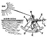 The
second critical component of celestial navigation is to measure the angle
formed at the observer's eye between the celestial body and the sensible
horizon. The sextant, an optical instrument, is used to perform this function.
The sextant consists of two primary assemblies. The frame is a rigid triangular
structure with a pivot at the top and a graduated segment of a circle, referred
to as the "arc", at the bottom. The second component is the index
arm, which is attached to the pivot at the top of the frame. At the bottom is
an endless vernier which clamps into teeth on the bottom of the
"arc". The optical system consists of two mirrors and, generally, a
low power telescope. One mirror, referred to as the "index mirror" is
fixed to the top of the index arm, over the pivot. As the index arm is moved,
this mirror rotates, and the graduated scale on the arc indicates the measured
angle ("altitude").
The
second critical component of celestial navigation is to measure the angle
formed at the observer's eye between the celestial body and the sensible
horizon. The sextant, an optical instrument, is used to perform this function.
The sextant consists of two primary assemblies. The frame is a rigid triangular
structure with a pivot at the top and a graduated segment of a circle, referred
to as the "arc", at the bottom. The second component is the index
arm, which is attached to the pivot at the top of the frame. At the bottom is
an endless vernier which clamps into teeth on the bottom of the
"arc". The optical system consists of two mirrors and, generally, a
low power telescope. One mirror, referred to as the "index mirror" is
fixed to the top of the index arm, over the pivot. As the index arm is moved,
this mirror rotates, and the graduated scale on the arc indicates the measured
angle ("altitude").
Adjustment of the sextant consists of checking and aligning all the optical elements to eliminate "index correction". Index correction should be checked, using the horizon or more preferably a star, each time the sextant is used. The practice of taking celestial observations from the deck of a rolling ship, often through cloud cover and with a hazy horizon, is by far the most challenging part of celestial navigation.
Inertial navigation
Inertial navigation
is a dead reckoning
type of navigation system that computes its position based on motion sensors.
Once the initial latitude and longitude is established, the system receives
impulses from motion detectors that measure the acceleration along three or
more axes enabling it continually and accurately to calculate the current
latitude and longitude. Its advantages over other navigation systems are that,
once the starting position is set, it does not require outside information, it
is not affected by adverse weather conditions and it cannot be detected or
jammed by the enemy. Its disadvantage is that since the current position is
calculated solely from previous positions, its errors are cumulative,
increasing at a rate roughly proportional to the time since the initial
position was input. So inertial navigation systems must be corrected frequently
with a location 'fix' from some other type of navigation system. The US Navy
developed a Ships Inertial Navigation System (SINS) during the Polaris missile program to insure a safe,
reliable and accurate navigation system for its missile submarines. Inertial
navigation systems were in wide use until satellite
navigation systems (GPS) became available.
Electronic navigation
Radio navigation
A radio direction
finder or RDF is a device for finding the direction to a radio
source. Due to radio's ability to travel very long distances "over the
horizon", it makes a particularly good navigation system for ships and
aircraft that might be flying at a distance from land.RDFs
works by rotating a directional antenna
and listening for the direction in which the signal from a known station comes
through most strongly. This sort of system was widely used in the 1930s and
1940s. RDF antennas are easy to spot on German World War II aircraft, as loops under the
rear section of the fuselage, whereas most US aircraft enclosed the antenna in a small
teardrop-shaped fairing.In navigational applications, RDF signals are provided in the form of radio beacons, the radio version of a lighthouse. The signal is typically a simple AM broadcast of a morse code series of letters, which the RDF can tune in to see if the beacon is "on the air". Most modern detectors can also tune in any commercial radio stations, which is particularly useful due to their high power and location near major cities.
The OMEGA Navigation System was the first truly global radio navigation system for aircraft, operated by the United States in cooperation with six partner nations. OMEGA was developed by the United States Navy for military aviation users. It was approved for development in 1968 and promised a true worldwide oceanic coverage capability with only eight transmitters and the ability to achieve a four mile accuracy when fixing a position. Initially, the system was to be used for navigating nuclear bombers across the North Pole to
LORAN is a terrestrial navigation system using low frequency radio transmitters that use the time interval between radio signals received from three or more stations to determine the position of a ship or aircraft. The current version of LORAN in common use is LORAN-C, which operates in the low frequency portion of the EM spectrum from 90 to 110 kHz. Many nations are users of the system, including the United States, Japan, and several European countries.
Radar navigation
Radar ranges and
bearings can be very useful navigation.
When
a vessel is within radar range of land or special radar aids to navigation, the
navigator can take distances and angular bearings to charted objects and use
these to establish arcs of position and lines of position on a chart.[11] A fix consisting of only radar
information is called a radar fix.[12]Parallel indexing is a technique defined by William Burger in the 1957 book The Radar Observer's Handbook.[14] This technique involves creating a line on the screen that is parallel to the ship's course, but offset to the left or right by some distance.[14] This parallel line allows the navigator to maintain a given distance away from hazards.[14]
Some techniques have been developed for special situations. One, known as the "contour method," involves marking a transparent plastic template on the radar screen and moving it to the chart to fix a position.[15]
Another special technique, known as the Franklin Continuous Radar Plot Technique, involves drawing the path a radar object should follow on the radar display if the ship stays on its planned course.[16] During the transit, the navigator can check that the ship is on track by checking that the pip lies on the drawn line.[16]
Satellite navigation
Global
Navigation Satellite System or GNSS is the term for satellite navigation
systems that provide positioning with global coverage. A GNSS allow small electronic receivers to determine their
location (longitude, latitude, and altitude) to within a few metres
using time signals transmitted along a line of sight
by radio from satellites. Receivers on the ground with a
fixed position can also be used to calculate the precise time as a reference
for scientific experiments.As of 2007, the United States NAVSTAR Global Positioning System (GPS) is the only fully operational GNSS. The Russian GLONASS is a GNSS in the process of being restored to full operation. The European Union's Galileo positioning system is a next generation GNSS in the initial deployment phase, scheduled to be operational in 2010. China has indicated it may expand its regional Beidou navigation system into a global system.
More than two dozen GPS satellites are in medium Earth orbit, transmitting signals allowing GPS receivers to determine the receiver's location, speed and direction.
Since the first experimental satellite was launched in 1978, GPS has become an indispensable aid to navigation around the world, and an important tool for map-making and land surveying. GPS also provides a precise time reference used in many applications including scientific study of earthquakes, and synchronization of telecommunications networks.
Developed by the United States Department of Defense, GPS is officially named NAVSTAR GPS (NAVigation Satellite Timing And Ranging Global Positioning System). The satellite constellation is managed by the United States Air Force 50th Space Wing. The cost of maintaining the system is approximately US$750 million per year,[17] including the replacement of aging satellites, and research and development. Despite this fact, GPS is free for civilian use as a public good.
Navigation processes
Day's work in navigation
The
Day's work in navigation is a minimal set of tasks consistent with prudent
navigation. The definition will vary on military and civilian vessels, and from
ship to ship, but takes a form resembling:[18]- Maintain
continuous dead reckoning plot.
- Take two
or more star observations at morning twilight for a celestial fix. (prudent
to observe 6 stars)
- Morning
sun observation. Can be taken on or near prime vertical for longitude, or at
any time for a line of position.
- Determine
compass error by azimuth observation of the sun.
- Computation
of the interval to noon, watch time of local apparent noon, and constants
for meridian or ex-meridian sights.
- Noontime
meridian or ex-meridian observation of the sun for noon latitude line.
Running fix or cross with Venus line for noon fix.
- Noontime
determination the day's run and day's set and drift.
- At least
one afternoon sun line, in case the stars are not visible at twilight.
- Determine
compass error by azimuth observation of the sun.
- Take two
or more star observations at evening twilight for a celestial fix.
(prudent to observe 6 stars)
Passage planning
Passage
planning or voyage planning is a procedure to develop a complete description of
vessel's voyage from start to finish. The plan includes leaving the dock and
harbor area, the enroute portion of a voyage, approaching the destination, and mooring.
According to international law, a vessel's captain is
legally responsible for passage planning,[19] however on larger vessels, the
task will be delegated to the ship's navigator.[20]Studies show that human error is a factor in 80 percent of navigational accidents and that in many cases the human making the error had access to information that could have prevented the accident.[20] The practice of voyage planning has evolved from penciling lines on nautical charts to a process of risk management.[20]
 Passage
planning consists of three stages: appraisal, planning, execution, and
monitoring,[20] which are specified in International
Maritime Organization Resolution A.893(21), Guidelines For Voyage
Planning,[21] and these guidelines are
reflected in the local laws of IMO signatory countries (for example, Title 33
of the U.S. Code of
Federal Regulations), and a number of professional books or
publications. There are some fifty elements of a comprehensive passage plan
depending on the size and type of vessel.
Passage
planning consists of three stages: appraisal, planning, execution, and
monitoring,[20] which are specified in International
Maritime Organization Resolution A.893(21), Guidelines For Voyage
Planning,[21] and these guidelines are
reflected in the local laws of IMO signatory countries (for example, Title 33
of the U.S. Code of
Federal Regulations), and a number of professional books or
publications. There are some fifty elements of a comprehensive passage plan
depending on the size and type of vessel.The appraisal stage deals with the collection of information relevant to the proposed voyage as well as ascertaining risks and assessing the key features of the voyage. In the next stage, the written plan is created. The third stage is the execution of the finalised voyage plan, taking into account any special circumstances which may arise such as changes in the weather, which may require the plan to be reviewed or altered. The final stage of passage planning consists of monitoring the vessel's progress in relation to the plan and responding to deviations and unforeseen circumstances.
Integrated bridge systems
Electronic
integrated bridge concepts are driving future navigation system planning.[7] Integrated systems take inputs
from various ship sensors, electronically display positioning information, and
provide control signals required to maintain a vessel on a preset course. The navigator becomes a system manager,
choosing system presets, interpreting system output, and monitoring vessel
response.
Pilotage
Pilotage is the use of
fixed visual references on the ground or sea by means of sight or radar to
guide oneself to a destination, sometimes with the help of a map
or nautical chart. People use pilotage for
activities such as guiding vessels and aircraft, hiking and Scuba diving. When visual references are
not available, it is necessary to use an alternative method of navigation such as dead reckoning (typically with a compass), radio navigation, and satellite
navigation (such as GPS).
Difficulties
Pilotage
depends on the pilot being able to recognise the visual references in order to
make use of them. The pilot must either be familiar with those visual
references or be able to discover them from a map,
aeronautical chart
or nautical chart. Many nautical and
aeronautical disasters have resulted from the pilot incorrectly identifying
visual references.Poor visibility may affect safe navigation by obscuring the natural features used by pilots in an area. In such situations, pilots use navigational aids such as radar and the GPS to determine position and monitor their passage.
Visual features
Common
types of visual reference point used for pilotage:During the day:
- Natural features: Mountains, hills, lakes, rivers and coastal features such as cliffs, rocks and beaches
- Man made nautical features: sea marks, land marks and radio aerials
- Man made land features: Airports, cities, dams
and highways
- Man made nautical features: Lighthouses, lightships and sea marks with lights
- Man made land features: Airports, illuminated towers and buildings
Tugboat
Seagoing tugboats are in three basic categories:
- The
standard seagoing tugboat with model bow that tows its "payload"
on a hawser (long steel or soft fiber rope).
- The
"notch tug" which can be secured in a notch at the stern of a
specially designed barge, effectively making the combination a ship. This
configuration, however, is dangerous to use with a barge which is "in
ballast" (no cargo) or in a head or following sea. Therefore, the
"notch tugs" are usually built with a towing winch. With this
configuration, the barge being pushed might approach the size of a small
ship, the interaction of the water flow allows a higher speed with a
minimal increase in power required or fuel consumption.
- The
"integral unit," "integrated tug and barge," or
"ITB," comprises specially designed vessels that lock together
in such a rigid and strong method as to be certified as such by
authorities (classification societies) such as the American
Bureau of Shipping. Lloyd's
Register of Shipping, Indian
Register of Shipping, Det Norske
Veritas or several others. These units stay combined under
virtually any sea conditions and the "tugs" usually have poor
sea keeping designs for navigation without their "barges"
attached. Vessels in this category are legally considered to be ships
rather than tugboats and barges must be staffed accordingly. Such vessels
must show navigation lights compliant with those required of ships rather
than those required of tugboats and vessels under tow. Articulated tug and
barge units also utilize mechanical means to connect to their barges.
ATB's generally utilize Intercon and Bludworth connection systems. ATB's
are generally staffed as a large tugboat, with between seven to nine crew
members. The typical American ATB operating on the east coast, per custom,
displays navigational lights of a towing vessel pushing ahead, as
described in the '72 COLREGS.
River tugs River tugs are also referred to as towboats or pushboats. Their hull designs would make open ocean operations dangerous. River tugs usually do not have any significant hawser or winch. Their hulls feature a flat front or bow to line up with the rectangular stern of the barge.
Tugboat propulsion
Tugboat
engines typically produce 500 to 2,500 kW (~ 680 to 3,400 hp), but larger boats (used in deep waters)
can have power ratings up to 20,000 kW (~ 27,200 hp) and usually have
an extreme power:tonnage-ratio (normal cargo and passenger ships have a P:T-ratio
(in kW:GRT)
of 0.35 to 1.20, whereas large tugs typically are 2.20 to 4.50 and small
harbour-tugs 4.0 to 9.5). The engines are often the same as those used in railroad locomotives, but typically drive the propeller mechanically instead of
converting the engine output to power electric motors, as is common for
railroad engines. For safety, tugboats' engines often feature two of each
critical part for redundancy.[1]A tugboat's power is typically stated by its engine's horsepower and its overall bollard pull.
Diagram with components named
 Tugboats
are highly maneuverable, and various propulsion systems have been developed to
increase maneuverability and increase safety. The earliest tugs were fitted
with paddle wheels,
but these were soon replaced by propeller-driven tugs. Kort nozzles have been added to increase
thrust per kW/hp. This was followed by the nozzle-rudder, which omitted the
need for a conventional rudder. The cycloidal propeller was developed prior to World War II and was occasionally used in
tugs because of its maneuverability. After World War II it was also linked to
safety due to the development of the Voith Water Tractor, a tugboat
configuration which could not be pulled over by its tow. In the late 1950s, the
Z-drive or (azimuth thruster) was developed. Although
sometimes referred to as the Schottel system, many brands exist: Schottel,
Z-Peller,
Duckpeller,
Thrustmaster, Ulstein, Wärtsilä, etc. The propulsion systems are
used on tugboats designed for tasks such as ship docking and marine
construction. Conventional propeller/rudder configurations are more efficient
for port-to-port towing.
Tugboats
are highly maneuverable, and various propulsion systems have been developed to
increase maneuverability and increase safety. The earliest tugs were fitted
with paddle wheels,
but these were soon replaced by propeller-driven tugs. Kort nozzles have been added to increase
thrust per kW/hp. This was followed by the nozzle-rudder, which omitted the
need for a conventional rudder. The cycloidal propeller was developed prior to World War II and was occasionally used in
tugs because of its maneuverability. After World War II it was also linked to
safety due to the development of the Voith Water Tractor, a tugboat
configuration which could not be pulled over by its tow. In the late 1950s, the
Z-drive or (azimuth thruster) was developed. Although
sometimes referred to as the Schottel system, many brands exist: Schottel,
Z-Peller,
Duckpeller,
Thrustmaster, Ulstein, Wärtsilä, etc. The propulsion systems are
used on tugboats designed for tasks such as ship docking and marine
construction. Conventional propeller/rudder configurations are more efficient
for port-to-port towing.The Kort nozzle is a sturdy cylindrical structure around a special propeller having minimum clearance between the propeller blades and the inner wall of the Kort nozzle. The thrust:power ratio is enhanced because the water approaches the propeller in a linear configuration and exits the nozzle the same way. The Kort nozzle is named after its inventor, but many brands exist.
A recent Dutch innovation is the Carousel Tug, winner of the Maritime Innovation Award at the Dutch Maritime Innovation Awards Gala in 2006[2]. The Carousel Tug adds a pair of interlocking rings to the body of the tug, the inner ring attached to the boat, with the outer ring attached to the towed ship by winch or towing hook. Since the towing point rotates freely, the tug is very difficult to capsize[3].
The Voith Schneider propeller (VSP), also known as a cycloidal drive is a specialized marine propulsion system. It is highly maneuverable, being able to change the direction of its thrust almost instantaneously. It is widely used on tugs and ferries.
From a circular plate, rotating around a vertical axis, a circular array of vertical blades (in the shape of hydrofoils) protrude out of the bottom of the ship. Each blade can rotate itself around a vertical axis. The internal gear changes the angle of attack of the blades in sync with the rotation of the plate, so that each blade can provide thrust in any direction, very similar to the collective pitch control and cyclic in a helicopter.
No comments:
Post a Comment